Chapter 1: Introduction
- What is software engineering?
- Software engineering is an engineering discipline that is concerned with all aspects of software production from the early stages of system specification through to maintaining the system after it has gone into use
- They adopt a systematic and organized approach to their work, since it is the most effective wat to produce high-quality software
- Why software engineering is important?
- More and more, individuals and society rely on advanced software systems. We need to be able to produce reliable and trustworthy systems economically and quickly.
- It is usually cheaper, in the long run, to use software engineering methods and techniques for professional software systems rather than just write programs as a personal programming project. Failure to use software engineering method leads to higher costs for testing, quality assurance, and long-term maintenance.
- Steps in software engineering (software process)
- Software specification, where customers and engineers define the software that is to be produced and the constraints on its operation.
- Software development, where the software is designed and programmed.
- Software validation, where the software is checked to ensure that it is what the customer requires.
- Software evolution, where the software is modified to reflect changing customer
and market requirements.
- Issues that affect many software
- Heterogeneity: Systems must run on diverse devices and integrate with older software, requiring flexible and dependable solutions.
- Business and Social Change: Rapid economic and technological changes demand quick software adaptation, necessitating faster development methods.
- Security and Trust: Ensuring software security and trustworthiness is vital, especially for remote systems accessed via web interfaces.
- Scale: Software must accommodate a wide range of scales, from small embedded systems to large cloud-based systems serving global users.
- Types of application (different types may require different engineering technique)
- Stand-alone applications: These run on personal computers or mobile devices and include all necessary functionality, like office apps, CAD programs, and productivity apps.
- Interactive transaction-based applications: These execute on remote computers and are accessed by users for activities like e-commerce, business systems via web browsers or special clients, and cloud-based services.
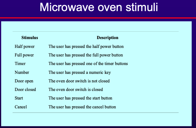
- Embedded control systems: Software systems that control hardware devices, found in mobile phones, car anti-lock braking systems, and microwave ovens.
- Batch processing systems: Business systems that process large data batches, like periodic billing systems and salary payment systems.
- Entertainment systems: Personal use systems primarily for entertainment, often games running on specialized console hardware.
- Systems for modeling and simulation: Developed by scientists and engineers to model physical processes or situations, often requiring high-performance parallel systems.
- Data collection and analysis systems: Collect data from environments, interact with sensors, and process data, including “big data” analysis in cloud-based systems.
- Systems of systems: Composed of multiple software systems, used in large enterprises, with some being generic software products like ERP systems and others specially developed for the environment.
- Fundamentals of software engineering
- Managed Development Process: Software development should follow a planned and understood process tailored to the specific type of software being developed.
- Dependability and Performance: Software should be reliable, available, safe, and secure against external attacks. It should also perform efficiently without wasting resources.
- Software Specification and Requirements: Understanding and managing software specifications and requirements are crucial. This involves aligning customer and user expectations to deliver a useful system within budget and schedule.
- Effective Resource Utilization: Utilize existing resources effectively by reusing software whenever possible instead of developing entirely new solutions.
- Software engineering ethics - Key areas of ethical responsibility - Confidentiality: Software engineers should respect the confidentiality of their employers or clients, even without formal agreements. - Competence: Engineers should not misrepresent their skills and should only accept work within their competence level. - Intellectual Property: Engineers must be aware of and comply with intellectual property laws to protect the rights of employers and clients. - Computer Misuse: Engineers should not misuse others’ computers, ranging from trivial actions like unauthorized game playing to serious offenses like spreading malware. - ACM/IEE Code of Ethics 1. PUBLIC — Software engineers shall act consistently with the public interest. 2. CLIENT AND EMPLOYER — Software engineers shall act in a manner that is in the best interests of their client and employer consistent with the public interest 3. PRODUCT — Software engineers shall ensure that their products and related modifications meet the highest professional standards possible. 4. JUDGMENT — Software engineers shall maintain integrity and independence in their professional judgment. 5. MANAGEMENT — Software engineering managers and leaders shall subscribe to and promote an ethical approach to the management of software development and maintenance. 6. PROFESSION — Software engineers shall advance the integrity and reputation of the profession consistent with the public interest. 7. COLLEAGUES — Software engineers shall be fair to and supportive of their colleagues. 8. SELF — Software engineers shall participate in lifelong learning regarding the practice of their profession and shall promote an ethical approach to the practice of the profession.
Chapter 2: Software Processes
-
Software process is a set of related activities that leads to the production of a software system
-
4 fundamental software process
- Software Specification: Defining the functionality and operational constraints of the software.
- Software Development: Producing the software according to the specified requirements.
- Software Validation: Validating the software to ensure it meets the customer’s expectations and requirements.
- Software Evolution: Continuously updating and improving the software to adapt to changing customer needs and technological advancements.
-
Software Development Life Cycle
- A simplified representation of a software process
- Models
- Waterfall model
- derived from engineering process models used in large military systems engineering
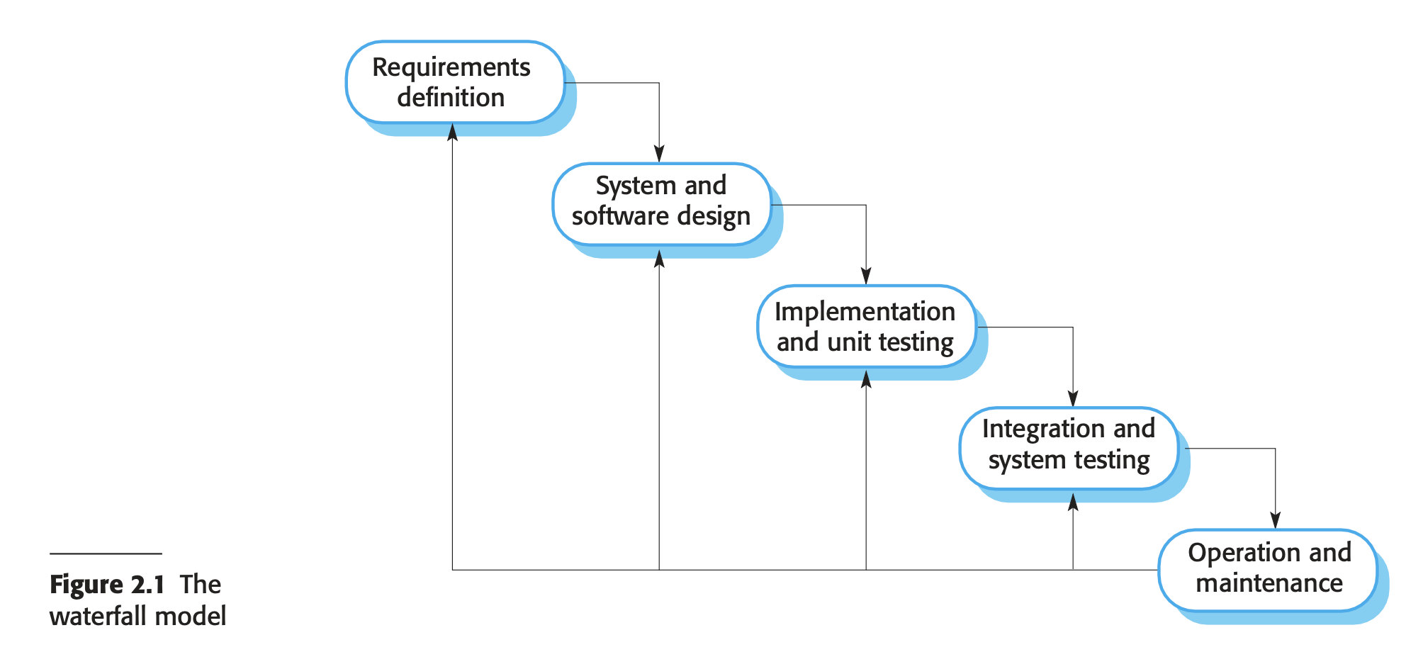
- stages
- Requirements Analysis and Definition: Consultation with system users to establish services, constraints, and goals, which are then detailed into a system specification.
- System and Software Design: Allocation of requirements to hardware or software, establishment of system architecture, and identification of software system abstractions and their relationships.
- Implementation and Unit Testing: Realization of software design into programs or program units, followed by unit testing to verify that each unit meets its specification.
- Integration and System Testing: Integration of individual program units into a complete system and testing to ensure software requirements are met before delivery to the customer.
- Operation and Maintenance: The system is installed, put into practical use, and undergoes ongoing maintenance involving error corrections, system unit improvements, and service enhancements based on new requirements.
- Since it isn’t flexible (cant acommodate change during development), it is only suitable for
- In embedded systems, decisions about software functionality must be made early due to hardware limitations.
- Critical systems require complete specification and design documents for thorough safety and security analysis, as correcting issues later can be costly.
- Large software systems in collaborative environments benefit from common models for hardware and software, enabling independent development of subsystems.
- Incremental development
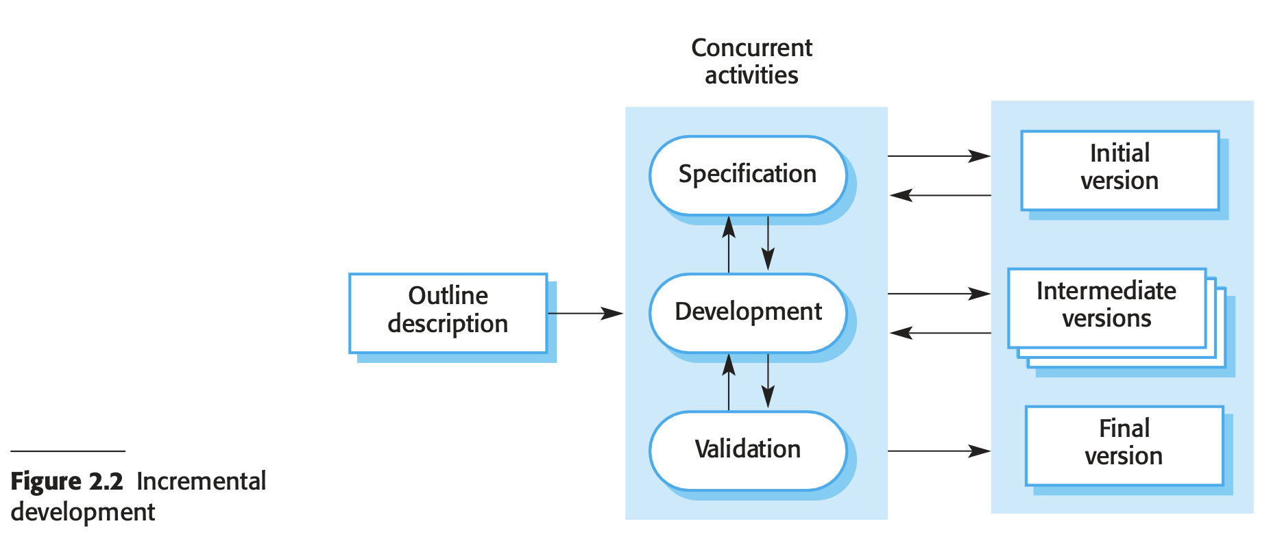
- Advantages of incremental development
- Reduced cost for implementing requirements changes compared to the waterfall model.
- Easier access to customer feedback through software demonstrations, aiding in progress assessment and adjustments.
- Disadvantages of incremental development:
- Challenges in large organizations due to bureaucratic procedures conflicting with agile processes, potentially hindering smooth implementation.
- Difficulty in judging progress for customers from software design documents, leading to potential misunderstandings or misalignment of expectations.
- Early delivery of software to customers may lack complete functionality, requiring careful management of customer expectations and value delivery.
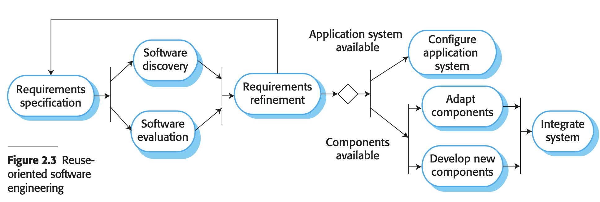
- Integration and configuration
- Rely on a base of reusable software components and an integrating framework for the composition of the components
- Types of software components that are frequently reused
- Stand-alone application systems adaptable to specific environments, offering extensive features but requiring customization for particular applications.
- Object collections designed as components or packages for integration into frameworks like Java Spring.
- Web services developed to service standards, accessible for remote invocation via the Internet.
- Stages
- Requirements Specification: Initial system requirements are proposed, including essential functionalities and desirable features.
- Software Discovery and Evaluation: Candidate components and systems are searched and evaluated based on outlined requirements to determine their suitability for the system.
- Requirements Refinement: Refinement of requirements occurs using information from discovered components and applications, adjusting the system specification accordingly. Alternative solutions may be sought if modifications are not feasible.
- Application System Configuration: If an off-the-shelf system meets requirements, it is configured for use in creating the new system.
- Component Adaptation and Integration: If no off-the-shelf solution is available, reusable components may be adapted or new components developed and integrated to form the system.
- Can reduce amount of software to be developed; reducing cost, risks; faster delivery of the software
- May not meet the real needs of user
- Process activities
- Software specification
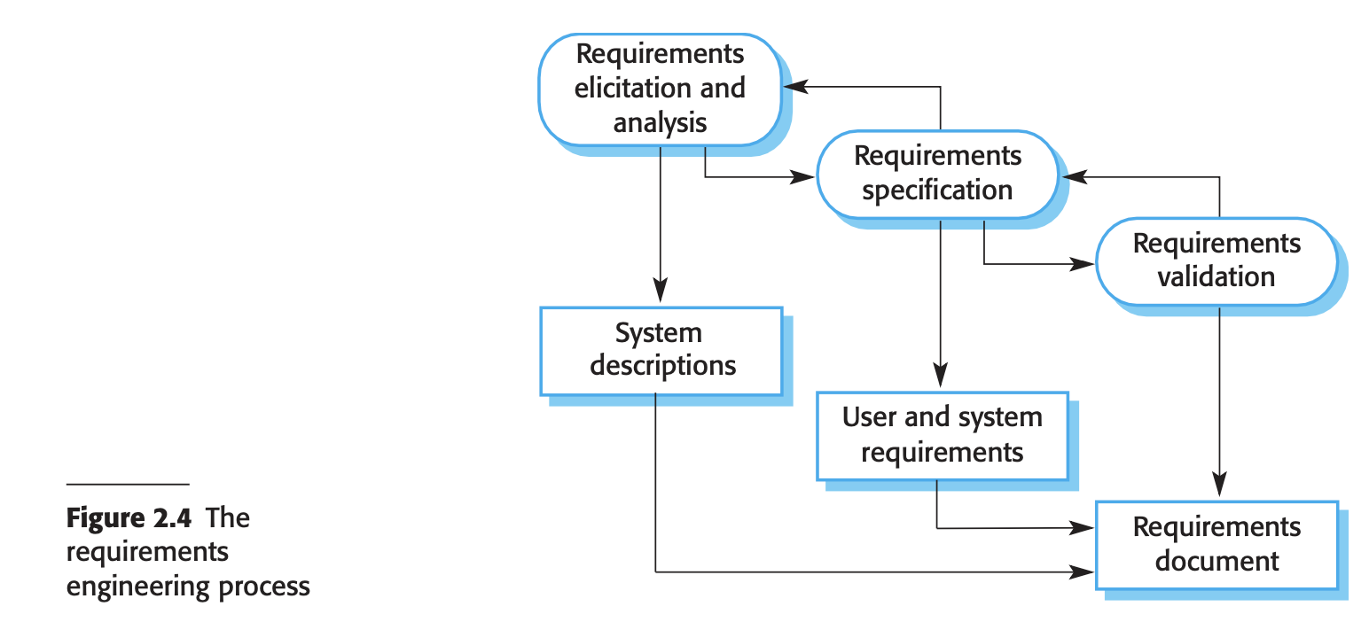
- Requirements Elicitation and Analysis: Deriving system requirements through observation, discussions, task analysis, and system modeling or prototyping.
- Requirements Specification: Translating gathered information into a document defining user and system requirements.
- Requirements Validation: Checking requirements for realism, consistency, and completeness, and correcting errors in the document.
- Software design and implementation
- Designing
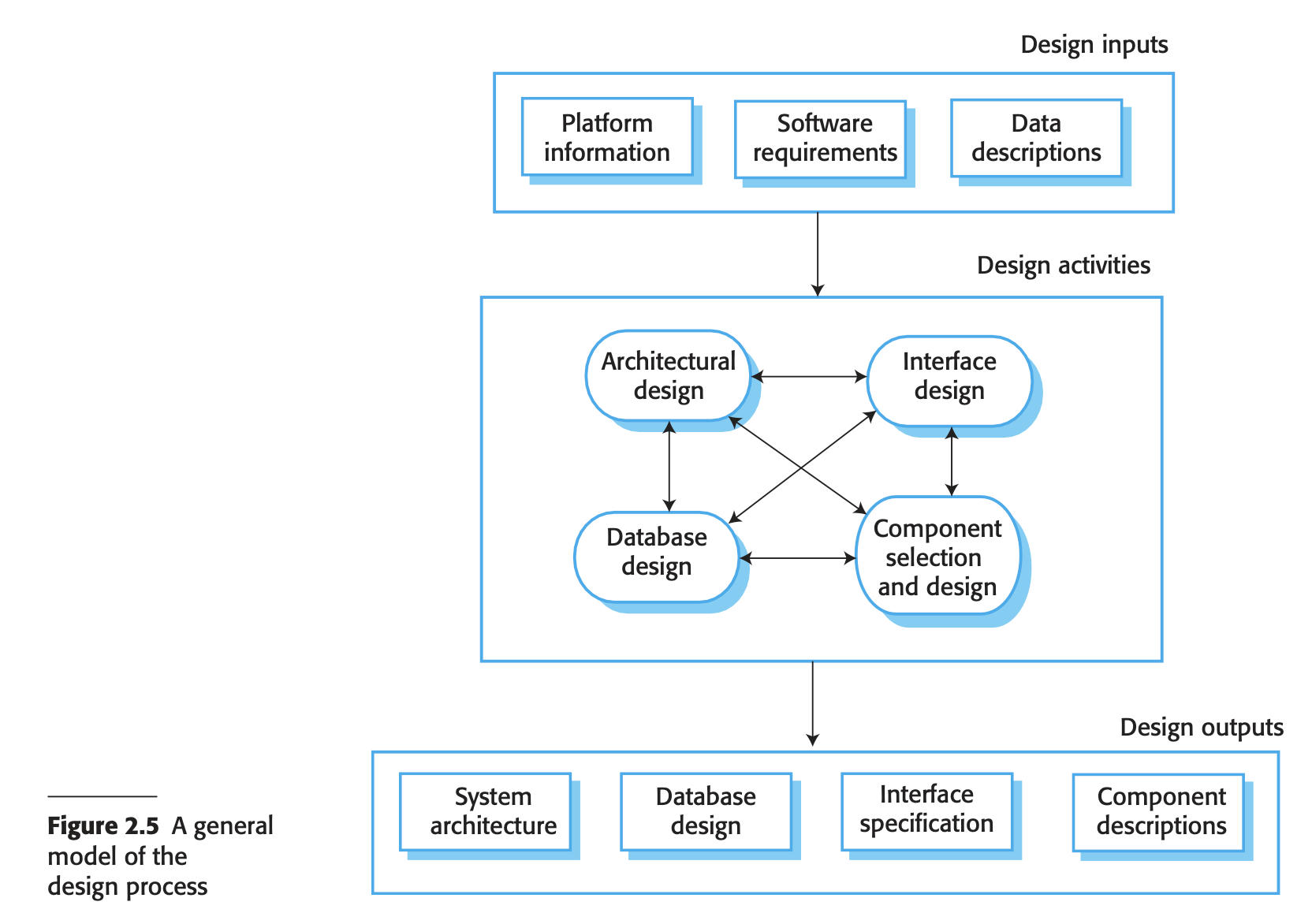
- Architectural Design: Identifying the system’s overall structure, key components, their relationships, and distribution.
- Database Design: Creating data structures and their representation in a database, depending on reusing an existing database or developing a new one.
- Interface Design: Defining clear interfaces between system components to enable their use without knowledge of internal implementation.
- Component Selection and Design: Finding reusable components or designing new ones, with design ranging from simple descriptions to detailed models like UML for implementation guidance.
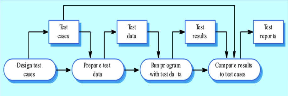
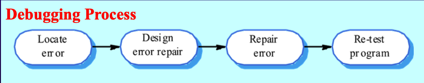
- Programming
- No specific stage
- Will carry out test to detect program defects (bugs); then fix it (debugging)
- Software validation (verification & validation (v&v))
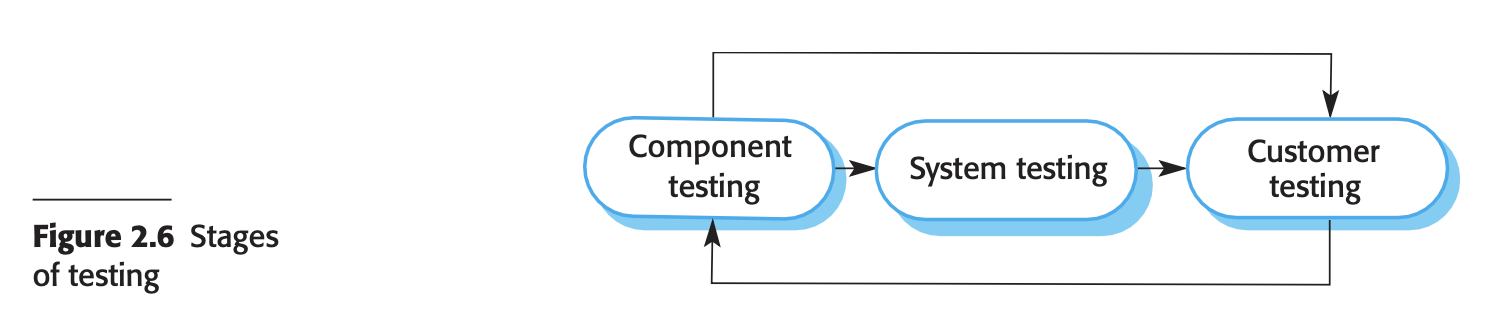
- Stages
- Component Testing: Individual system components are tested independently by developers, using tools like JUnit for automation. This includes testing functions, object classes, or groups of these entities.
- System Testing: Integrated system components are tested to identify errors from interactions and interface issues. It ensures the system meets functional and non-functional requirements, testing overall system properties. Larger systems may undergo staged integration testing.
- Customer Testing: Final testing before operational use, conducted by the system’s customer. It reveals real-world issues not captured by simulated test data, such as errors in requirements, system performance, or alignment with user needs for custom-built software or products.
- For a plan-driven software process, testing is driven by a set of test plan
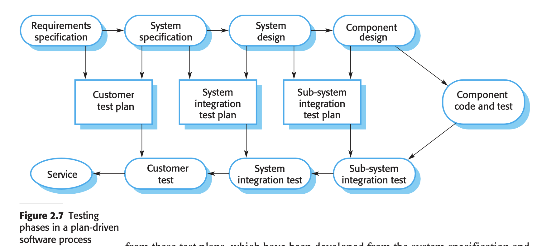
- Independent testing teams execute these plans, which are integral to development activities
- This approach aligns with the V-model, where testing activities correspond to stages in the waterfall process model.
- For software products intended for market release, beta testing is common
- This involves delivering the system to potential customers who provide feedback by using the software in real-world scenarios,
- Beta testing helps detect unanticipated errors and informs modifications before general release or further testing phases.
- Software evolution
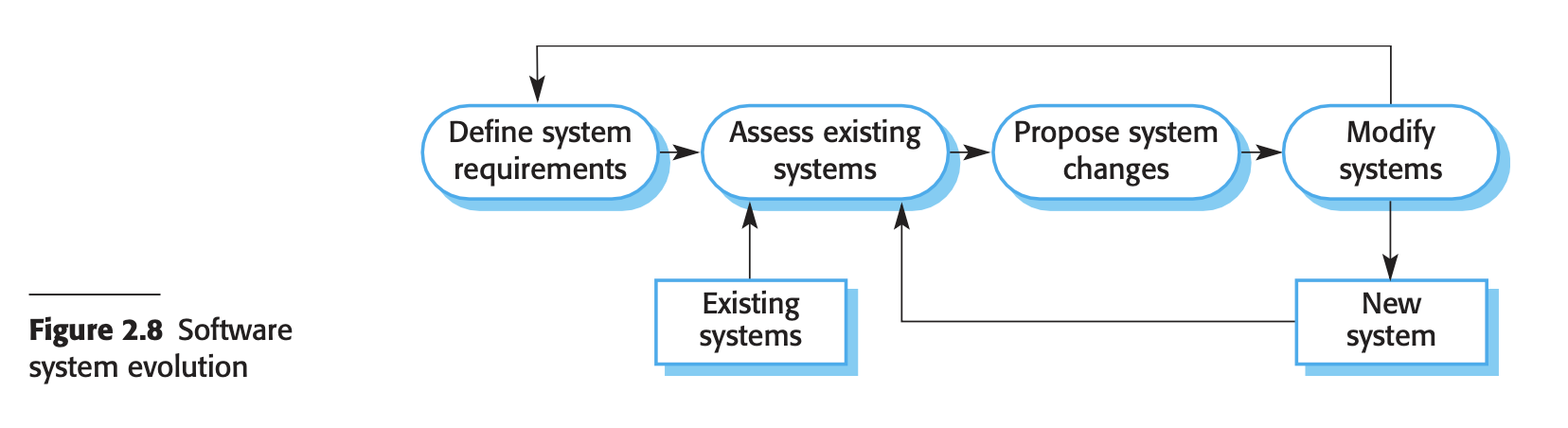
- Software’s flexibility and cost-effectiveness compared to hardware have led to its increased use in complex systems. The traditional division between software development and maintenance is blurring, as both are seen as part of an evolutionary process. Continuous software changes are made to meet evolving requirements and customer needs.
-
Coping with change
- Change is a constant in large software projects due to evolving requirements, new technologies, and business dynamics. This necessitates software processes that can accommodate changes without excessive rework, which adds to development costs.
- Two related approaches are used to reduce rework costs:
- Change anticipation involves activities that predict possible changes before significant rework is needed. For instance, prototyping allows customers to refine requirements before extensive software production, reducing the need for major changes later.
- Change tolerance involves designing processes and software to easily incorporate changes. Incremental development allows proposed changes to be implemented in stages, minimizing the impact on already developed parts of the system.
- 2 ways of coping with change and changing system requirements
- Prototyping
- Prototyping Process Overview:
- Requirements Engineering Process:
- Prototypes assist in eliciting and validating system requirements.
- System Design Process:
- Prototypes explore software solutions and aid in developing user interfaces.
- System Prototype Benefits:
- User Understanding:
- Allows potential users to see how well the system supports their work.
- Users may propose new requirements based on prototype usage.
- Error Identification:
- Reveals errors and omissions in system requirements during development.
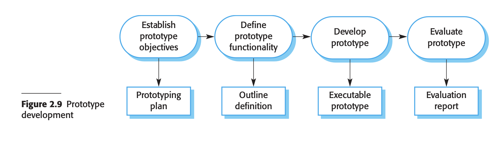
- Prototype Development Process:
- Objectives Definition:
- Explicitly state the objectives of prototyping (e.g., user interface development, validation of functional requirements, or demonstrating the application).
- Prototype Content:
- Decide what to include and exclude in the prototype system to control costs and accelerate delivery.
- May relax non-functional requirements for faster development.
- Prototype Evaluation:
- Conduct user training during evaluation.
- Derive an evaluation plan based on prototype objectives.
- Address challenges like user adaptation to the system and potential differences between prototype usage and final system usage.
- Incremental delivery
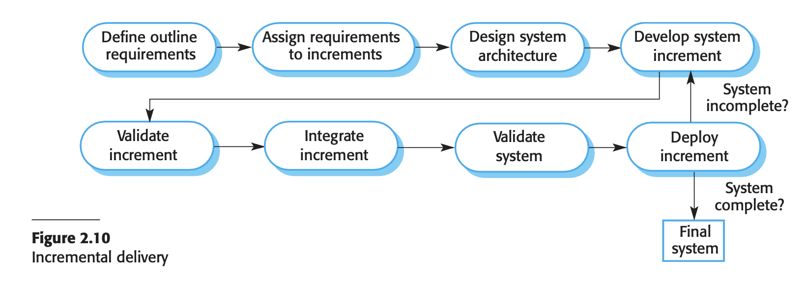
- Incremental Delivery Process:
- Customer Prioritization:
- Customers prioritize system services, defining high-priority services for early delivery.
- Incremental Definition:
- Incremental delivery involves defining service increments, with each increment providing a subset of system functionality based on service priority.
- Increment Development:
- Detailed requirements for the first increment are defined and developed without accepting changes for the current increment during development.
- Increment Deployment:
- Completed increments are delivered and integrated with existing ones in the customer’s working environment.
- Customers experiment with the system, clarifying requirements for later increments.
- Advantages of Incremental Delivery:
- Prototyping Benefits:
- Early increments serve as prototypes, helping customers gain experience and refine requirements for subsequent increments without relearning.
- Immediate Value:
- Customers gain value from the first increment, satisfying critical requirements immediately.
- Ease of Change:
- Incremental delivery maintains the benefits of incorporating changes into the system relatively easily.
- Challenges with Incremental Delivery:
- Replacement Systems:
- Iterative delivery is challenging when replacing existing systems as users typically require full functionality and may be unwilling to experiment with incomplete new systems.
- Common Facilities Identification:
- Identifying common facilities needed by all increments can be difficult as requirements are defined incrementally.
- Procurement Model Conflict:
- Conflicts arise with traditional procurement models where a complete system specification is expected upfront, whereas incremental delivery involves evolving specifications over increments.
- Applicability of Incremental Delivery:
- Incremental delivery is suitable for new systems where evaluators can experiment, but it may not work well for replacing existing systems or very large, complex systems with interdependent requirements. In such cases, a system prototype may be used to experiment and refine definitive requirements before implementation.
-
Process improvement - Why? - Driven by industry demands for cheaper, better software delivered faster - Involves understanding existing processes and making changes to enhance product quality, reduce costs, and accelerate development. - Approaches to Process Improvement: 1. Process Maturity Approach: - Focuses on improving process and project management, adopting good software engineering practices. - Aims for improved product quality and process predictability. 2. Agile Approach: - Emphasizes iterative development, reducing overheads in the software process. - Prioritizes rapid delivery of functionality and responsiveness to changing customer requirements. - Process Improvement Cycle:
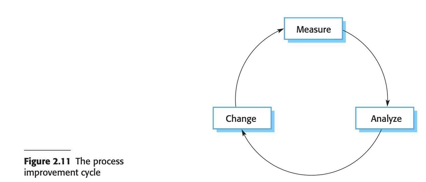
1. **Process Measurement**:
- Measure attributes of the software process or product as a baseline for improvement evaluation.
2. **Process Analysis**:
- Assess the current process, identify weaknesses, and develop process models.
3. **Process Change**:
- Propose and introduce process changes to address identified weaknesses.
4. **Measure Changes**:
- Re-measure attributes to evaluate the effectiveness of process improvements.
- **Process Maturity Levels**:

- Introduced by the Software Engineering Institute (SEI) to assess software engineering capability of defence contractor
- Five levels: Initial, Managed, Defined, Quantitatively Managed, Optimizing, focusing on increasing organizational standardization and process improvement.
- **Impact of Process Maturity**:
- Significant improvements in software engineering capability.
- More suitable for large companies due to overheads and complexity.
Chapter 3: SE practices
-
SE practices
- Based on George Polya’s approach in “How to Solve It”
- Understand the Problem (Communication and Analysis):
- Identify stakeholders and unknowns.
- Determine required data, functions, and features.
- Break down the problem into smaller, manageable parts.
- Represent the problem graphically if possible.
- Plan a Solution (Modeling and Software Design):
- Recognize patterns and reusable elements from similar problems.
- Define subproblems and potential solutions.
- Create a design model for effective implementation.
- Carry Out the Plan (Code Generation):
- Follow the design as a roadmap, making adjustments as necessary.
- Ensure the solution conforms to the design and is provably correct.
- Examine the Result (Testing and Quality Assurance):
- Implement a thorough testing strategy.
- Validate the solution against stakeholder requirements.
-
David Hooker’s 7 general SE principles
- The Reason It All Exists: Software should provide value to its users. All decisions should support this primary goal.
- KISS (Keep It Simple, Stupid!): Design should be as simple as possible to facilitate understanding and maintenance. Simplicity often requires thoughtful effort.
- Maintain the Vision: A clear, consistent vision is crucial to prevent a project from becoming a disjointed patchwork. An empowered architect should enforce this vision.
- What You Produce, Others Will Consume: Consider the needs of those who will use, maintain, or document the system. Design and code with the understanding that others will need to comprehend and extend your work.
- Be Open to the Future: Design systems to be adaptable to changes, avoiding solutions that limit future modifications. Aim to solve general problems, not just specific ones.
- Plan Ahead for Reuse: Reuse of code and designs saves time and effort but requires careful planning and forethought.
- Think!: Thoughtful consideration before action leads to better results and valuable learning experiences. Recognizing knowledge gaps and researching answers enhances the overall quality of the system.
-
Principles that guied each framework activity - Communication principles 1. Listen: Focus on the speaker’s words without planning your response. Ask for clarification if needed but avoid interruptions and contentious behavior. 2. Prepare Before Communicating: Understand the problem and relevant jargon before meetings. Prepare an agenda if you are leading the meeting. 3. Facilitate the Activity: Have a facilitator to guide the discussion, mediate conflicts, and ensure adherence to communication principles. 4. Face-to-Face Communication: Prefer face-to-face meetings, supplemented by visual aids like drawings or documents. 5. Take Notes and Document Decisions: Assign someone to record all important points and decisions to prevent misunderstandings. 6. Strive for Collaboration: Encourage collaboration and consensus to leverage collective knowledge and build trust among team members. 7. Stay Focused and Modularize Discussion: Keep discussions focused on one topic at a time to avoid confusion and ensure resolution. 8. Draw a Picture if Something is Unclear: Use visual aids to clarify points when verbal communication is insufficient. 9. Move On When Needed: Recognize when to move on from a topic, whether it’s agreed upon, unresolved, or unclear, to maintain communication agility. 10. Negotiation is Not a Contest: Aim for win-win outcomes in negotiations, understanding that compromise is necessary for all parties involved. - Planning principles 1. Understand the Scope of the Project: Knowing the project’s destination is crucial for effective planning. 2. Involve Stakeholders: Engage stakeholders to set priorities and establish constraints, often requiring negotiation on delivery order, timelines, and other issues. 3. Recognize Iterative Planning: Plans should be flexible and subject to change as work progresses, with replanning occurring after each software increment based on user feedback. 4. Estimate Based on Current Knowledge: Provide effort, cost, and task duration estimates based on the current understanding of the work, acknowledging that vague information leads to unreliable estimates. 5. Consider Risk: Identify high-impact and high-probability risks and adjust the project plan and schedule to accommodate potential risk occurrences. 6. Be Realistic: Account for human factors, such as not working 100% efficiently every day, communication noise, omissions, ambiguities, changes, and inevitable mistakes. 7. Adjust Granularity: Plan tasks in detail for the near term (high granularity) and broadly for the distant future (low granularity) to accommodate potential changes. 8. Ensure Quality: Identify methods for ensuring quality, such as scheduling technical reviews or using pair programming, and explicitly define them in the plan. 9. Accommodate Change: Define how changes will be handled, including customer requests, their implementation timing, and assessing their impact and cost. 10. Track and Adjust the Plan Frequently: Monitor progress daily to identify issues early and make necessary adjustments to stay on schedule.
Effective planning involves the participation of the entire software team, ensuring everyone is committed to the plan.
- Modelling principles
    1. **Primary Goal:** The main objective is to build software, not just create models. Models should aid in delivering software quickly, avoiding those that slow the process or add little value.
    2. **Travel Light:** Create only necessary models to avoid excessive updates and focus time on construction (coding and testing).
    3. **Simplicity:** Produce the simplest model that adequately describes the problem or software to keep the resulting software simple, which makes it easier to integrate, test, and maintain.
    4. **Change-Friendly:** Build models that are easy to modify. Even though requirements will change, ensure the models are reasonably complete to avoid missing important features in the design.
    5. **Explicit Purpose:** Each model should have a clear purpose. If the purpose is not solid, do not spend time on that model.
    6. **Adaptation:** Tailor models to fit the specific system being developed, as different applications might require different modeling techniques.
    7. **Useful Over Perfect:** Aim for useful models rather than perfect ones. Avoid spending excessive effort on making models absolutely complete and consistent, focusing instead on moving forward in the software engineering process.
    8. **Flexible Syntax:** Focus on successful communication of content rather than strict adherence to model syntax. Consistent notation is helpful, but effective communication is key.
    9. **Instincts Matter:** Trust your instincts. Experienced software engineers should heed their subconscious signals if a model seems flawed, even if it looks correct on paper.
    10. **Early Feedback:** Review models with team members to gain feedback that can correct mistakes, clarify interpretations, and add omitted features or functions.
- Requirements modelling principles
    1. **Information Domain Representation:** Understand and represent the data that flow into, out of, and are stored within the system.
    2. **Function Definition:** Clearly define the software functions that provide user benefits and support internal processing, describing them at varying levels of detail.
    3. **Behavior Representation:** Represent the software's behavior in response to external events, driven by interactions with the environment.
    4. **Partitioning Models:** Use a layered approach to partition models, dividing complex problems into manageable subproblems for better understanding and problem-solving.
    5. **Essential Information to Implementation Detail:** Start with the end-user perspective, describing the problem's essence without considering the solution's implementation, and gradually move toward detailed implementation considerations.

    By applying these principles, software engineers can systematically approach problem-solving in requirements modeling, ensuring a thorough understanding of the problem before moving on to the design phase.

- Design modelling principles
    1. **Traceability to Requirements:** Ensure design elements are traceable to the requirements model.
    2. **System Architecture Consideration:** Begin with architectural considerations before addressing component-level issues.
    3. **Data Design Importance:** Design data structures as carefully as processing functions.
    4. **Interface Design:** Design interfaces (internal and external) with care to ensure efficiency, error minimization, and simplicity.
    5. **User Interface Design:** Prioritize ease of use and tune the user interface to end-user needs.
    6. **Functional Independence:** Ensure components are functionally independent and cohesive.
    7. **Loose Coupling:** Maintain low coupling between components to reduce error propagation and enhance maintainability.
    8. **Understandable Design Representations:** Ensure design models are easily understandable for effective communication.
    9. **Iterative Development:** Develop the design iteratively, striving for simplicity with each iteration.
- Construction principles
    - Coding principles
        - Preparation Principles

            Before writing any code, ensure the following:

            1. **Understand the Problem:** Clearly grasp the problem you're solving.
            2. **Understand Design Principles:** Be familiar with basic design concepts.
            3. **Choose the Right Language:** Select a programming language that suits the software's needs and operating environment.
            4. **Select the Right Environment:** Choose a programming environment with tools that facilitate your work.
            5. **Create Unit Tests:** Develop a set of unit tests to apply once the coding is complete.
        - Programming Principles

            While writing code, adhere to these guidelines:

            1. **Structured Programming:** Follow structured programming practices.
            2. **Pair Programming:** Consider using pair programming for better results.
            3. **Appropriate Data Structures:** Choose data structures that fit the design requirements.
            4. **Consistent Interfaces:** Ensure interfaces align with the software architecture.
            5. **Simple Conditional Logic:** Keep conditional logic straightforward.
            6. **Testable Nested Loops:** Write nested loops that are easy to test.
            7. **Meaningful Variable Names:** Use meaningful variable names and adhere to local coding standards.
            8. **Self-Documenting Code:** Write code that explains itself.
            9. **Visual Layout:** Use indentation and blank lines to enhance readability.
        - Validation Principles

            After completing your initial coding pass:

            1. **Code Walkthroughs:** Conduct code walkthroughs when necessary.
            2. **Perform Unit Tests:** Execute unit tests and fix any identified errors.
            3. **Refactor Code:** Refactor the code to improve its structure and readability.

    - Testing principle
        - Objectives of Software Testing (Glen Myers)
            1. **Finding Errors:** Testing aims to execute a program with the intent of uncovering errors.
            2. **High-Probability Test Cases:** Good test cases have a high likelihood of discovering previously unknown errors.
            3. **Successful Tests:** A test is deemed successful if it uncovers an error that has not been found before.
        - Testing Principles (Davis)
            1. **Traceability to Requirements:** All tests should be linked to customer requirements, ensuring that severe defects impacting the program's ability to meet its requirements are identified.
            2. **Early Test Planning:** Tests should be planned well before coding begins, starting with the completion of the requirements model and the solidification of the design model.
            3. **Pareto Principle Application:** Typically, 80% of all errors will be found in 20% of the program components. Identifying and thoroughly testing these components is crucial.
            4. **Progressive Testing:** Testing should start with individual components ("in the small") and gradually move to integrated clusters and the entire system ("in the large").
            5. **Infeasibility of Exhaustive Testing:** Due to the large number of possible path permutations in even moderately sized programs, exhaustive testing is impossible. However, it is feasible to cover program logic adequately and ensure all conditions in component-level designs are tested.
    - Deployment principles
        1. **Manage Customer Expectations:**
            - Clearly communicate what will be delivered to avoid customer disappointment.
            - Avoid sending conflicting messages about delivery promises to maintain trust and morale.
        2. **Complete Delivery Package:**
            - Assemble and test a complete package including all executable software, support files, documents, and installation scripts.
            - Test in various configurations to ensure compatibility and reliability.
        3. **Establish Support Regime:**
            - Prepare support materials and mechanisms before delivery to ensure responsiveness and accurate information for end users.
            - Maintain records for assessing support needs.
        4. **Provide Instructional Materials:**
            - Develop training aids, troubleshooting guidelines, and documentation highlighting new features.
            - Ensure users have the help materials they need.
        5. **Fix Bugs Before Delivery:**
            - Deliver high-quality software even if it means a slight delay.
            - Avoid releasing buggy software with promises of future fixes to maintain customer satisfaction and trust.
Chapter 4: System engineering
- System components
- Hardware
- Physical layer of the information system
- Software
- Programs that control the hardware and produce the desired results:
- System software: Manages hardware components
- Application software (programs that support day-to-day business functions)
- Data
- Raw material that been transformed into useful information - store in tables
- Process
- Tasks and business functions that users/ staffs perform to achieve specific results
- People
- People who have interest in an information system (from management to users)
- System development environment
- The people - system stakeholders
- System Owner - responsible for funding the project of developing,
operating and maintaining the system.-
- External Service Providers - a system analyst/designer/programmer who sells their expertise and experience (act as a consultant).
- Tester - evaluate the system’s compliance with its specified
requirements
- System user:
- Internal System Users: These are employees of the business, including clerical and service workers, as well as technical and professional staff.
- External System Users: These include customers, suppliers, and partners of the business.
- Project Manager - Ensures that the project is completed on time and within budget.
- Configuration Manager - Manages changes to hardware, software, and documentation throughout the system’s lifecycle.
- Systems Analyst - Determines how people, data, processes, and technology can best solve business problems.
- System Designer - Translates user requirements into technical solutions.
- System Developer/Programmer - Constructs systems and components based on design specifications.
- Business drivers
- e-Commerce - Buying and selling goods and services using the internet.
- e-Business - Using the internet to conduct and support daily business activities.
- Three Basic Types of e-Commerce and e-Business Applications:
- Marketing Products and Services through the Web
- Business-to-Consumer (B2C)
- Selling products or services to consumers through technologies like websites (e.g., Amazon, eBay).
- Business-to-Business (B2B) - Electronic and paperless transactions within or between businesses.
Web-based System
- Uses the web to market products and services.
Business Support System
- Manages day-to-day business transactions like sales and operations.
Knowledge Management System
- An expert system that helps manage business issues by combining, filtering, organizing, and analyzing information to assist managers in planning and operating the business.
- Technology drivers
Networks and the Internet
- Pervasive networking technologies based on the Internet, including xHTML, XML, scripting languages, web-specific programming languages, intranets, extranets, portals, and web services.
Mobile and Wireless Technologies
- Facilitate communication and connectivity to information systems using devices like PDAs, iPads, Blackberries, email, and Bluetooth.
Object Technologies
- Information systems built using object-oriented analysis and design, often with an agile approach.
Collaborative Technologies
- Enhance interpersonal communications and teamwork through email, instant messaging, groupware (across physical locations), and workflow tools for process execution.
- System engineering process
- Waterfall Model: Often followed due to the need for parallel development of different system parts.
- Limited iteration between phases as hardware changes are costly; software may need to compensate for hardware issues.
- Interdisciplinary Collaboration: Involves engineers from various disciplines who must work together.
- Different disciplines use distinct vocabularies, necessitating significant negotiation.
- Types of Critical Systems
- Safety-critical systems: Failure can cause loss of life, injury, or environmental damage (e.g., chemical plant protection systems, medical systems).
- Mission-critical systems: Failure results in the failure of a goal-directed activity (e.g., spacecraft navigation systems).
- Business-critical systems: Failure leads to significant economic losses (e.g., customer accounting systems in banks, NASDAQ trading systems).
- Safety Critical Properties
- Properties like performance and reliability are measurable.
- Important non-measurable properties:
- Safety: System should not behave unsafely.
- Security: System should prevent unauthorized use.
- Dependability
- Crucial for critical systems, reflecting users’ trust in the system.
- Dependability includes:
- Availability: System operational at a given time.
- Reliability: Failure-free operation over a specified time.
- Safety: Safe operation without causing harm.
- Security: Protection against unauthorized access.
- Repairability: Ease of repair after failure.
- Maintainability: Ease of adaptation to new requirements.
- Survivability: Operation under hostile conditions.
- Error Tolerance: Handling user input errors.
- Dependability costs increase exponentially with higher requirements.
- Reliability
- Influences include hardware reliability, software reliability, and operator reliability.
- Key terms:
- System failure: System does not deliver expected service.
- System error: Erroneous system state.
- System fault: Characteristic leading to errors.
- Human error: Actions introducing faults.
- Reliability and Availability
- Reliability: Probability of failure-free operation.
- Availability: Probability that the system is operational.
- Faults and Failures
- Failures result from system errors due to faults.
- Not all faults cause errors; not all errors lead to failures.
- Reliability Achievement
- Fault avoidance: Minimize or trap mistakes during development.
- Fault detection and removal: Verification and validation techniques.
- Fault tolerance: Run-time techniques to handle faults and errors.
- Safety
- Primary safety-critical systems: Direct threat from failures (e.g., airplane landing systems).
- Secondary safety-critical systems: Indirect threat from failures (e.g., drug administration systems).
- Security
- Essential for availability, reliability, and safety.
- Key terms:
- Exposure: Possible loss or harm.
- Vulnerability: System weakness.
- Attack: Exploitation of a vulnerability.
- Threat: Potential to cause loss or harm.
- Control: Measure reducing vulnerability.
- Security Assurance
- Vulnerability avoidance: Design to prevent vulnerabilities.
- Attack detection and elimination: Detect and neutralize attacks.
- Exposure limitation: Minimize damage from successful attacks.
Chapter 5: Project management
- What is Software Project Management?
- Activities Involved: Ensuring that software is delivered on time, on schedule, and in accordance with the requirements of the organizations developing and procuring the software.
- Importance: Software development is always subject to budget and schedule constraints set by the organization.
- What is Process Management?
- Definition: Documenting, managing, and continually improving the process of system development.
- Scope: Applied to all projects, concerning activities, deliverables, and quality standards.
- What is Project Management?
- Project Definition: A sequence of activities that must be completed on time, within budget, and according to specification.
- Project Management Definition: The process of scoping, planning, staffing, organizing, directing, reporting, and controlling the development of a system at a minimum cost within a specified time frame while satisfying customer specifications.
- Prerequisite: A well-defined system development process.
- Scope: For a single project, focusing on non-standardized and uniquely flexible ‘one-off’ projects.
- Causes of Successful Projects
- Acceptable quality to the customer.
- Delivered on time and within budget.
- Balance adjustments when any factor changes.
- Causes of Failed Projects
- Lack of upper-management commitment.
- Lack of organization’s commitment to the system development methodology.
- Shortcuts around the system development methodology.
- Poor expectations management (scope creep, feature creep).
- Premature commitment to a fixed budget and schedule.
- Poor estimating techniques and over-optimism.
- The mythical man-month issue.
- Inadequate people management skills.
- Failure to adapt to business change.
- Insufficient resources and poor estimating.
- Failure to manage to the plan.
- The PM Body of Knowledge
- Functions:
- Scoping: Defining project boundaries.
- Planning: Detailing tasks and activities.
- Estimating: Duration of each task.
- Scheduling: Scheduling all activities.
- Organizing: Defining roles.
- Directing: Directing and motivating team activities.
- Reporting: Reporting to management, users, and the team.
- Tools and Techniques:
- PERT Chart: Graphical network model for task interdependencies and risk identification.
- Gantt Chart: Bar chart for project tasks against a calendar.
- Activity charts: Show task dependencies and critical paths.
- PM Software: Microsoft Project, MacProject, GanttProject.
- Types of Project Plans
- Quality Plan: Quality procedures and standards.
- Validation Plan: Approach, resources, and schedule for system validation.
- Configuration Management Plan: Procedures and structures.
- Maintenance Plan: Maintenance requirements, costs, and efforts.
- Staff Development Plan: Skills and experience development for team members.
- Project Planning Process
- Steps:
- Establish project constraints.
- Make initial assessments of project parameters.
- Define project milestones and deliverables.
- Draw up a project schedule.
- Initiate activities according to the schedule.
- Review project progress and revise estimates.
- Update the project schedule as needed.
- Re-negotiate project constraints and deliverables if problems arise.
- The PM Life Cycle
- Negotiate Scope: Define project boundaries and deliverables.
- Identify Tasks: Break down into activities and tasks; use WBS (Work Breakdown Structure).
- Estimate Task Durations: Consider project size, resources, experience, and constraints.
- Specify Intertask Dependencies: Identify dependencies (FS, SS, FF, SF) and use charts for scheduling.
- Assign Resources: Allocate people, services, facilities, supplies, and budget.
- Direct the Team Effort: Manage people and team activities.
- Monitor and Control Progress: Track progress and manage changes.
- Assess Project Results and Experiences: Collect feedback and evaluate project success.
- Risk Management
- Definition: Identifying and planning to minimize risks.
- Process:
- Risk Identification: Identify project, product, and business risks.
- Risk Analysis: Assess the likelihood and consequences.
- Risk Planning: Develop plans to avoid or minimize risks.
- Risk Monitoring: Continuously monitor risks throughout the project.
- Potential Risks: Staff turnover, management change, hardware unavailability, requirements change, specification delays, size underestimation, CASE tool underperformance, technology change, and product competition.
Chapter 6: Requirements Engineerings
- Requirements Engineering (RE) is a critical phase in the software development lifecycle. It involves identifying, documenting, validating, and managing the requirements of a system to ensure that it meets the needs of users and stakeholders.
- Requirements vs Specification
- Requirements:
- Statement of what the system should do or the quality it must have.
- Clarified and documented to generate corresponding specifications.
- Specification:
- Detailed and precise description of the requirements, including design and behavior.
- Focuses on “what” the system should do, while design specifications focus on “how” it should do it.
- Example:
- Requirement: The car should have a maximum speed of at least 120 mph.
- Specification: Details on the design to ensure the car achieves this speed.
- Requirements Structure
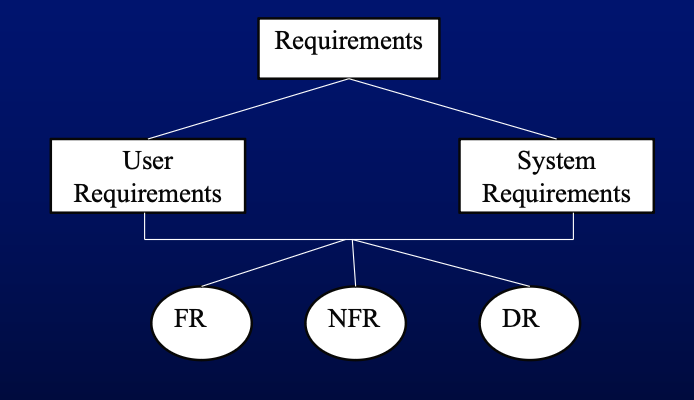
- User Requirements:
- High-level descriptions understandable by non-technical users.
- Examples: a system for a bank the user may require a function to calculate interest over a set time period.
- System Requirements:
- Detailed and technical specifications used for system design.
- Examples: The system must run on a server with IIS. File upload is limited to .xlsx format.
- Types of Requirements
- Functional Requirements:
- Describe services the system should provide and its behavior in various situations.
- Non-functional Requirements:
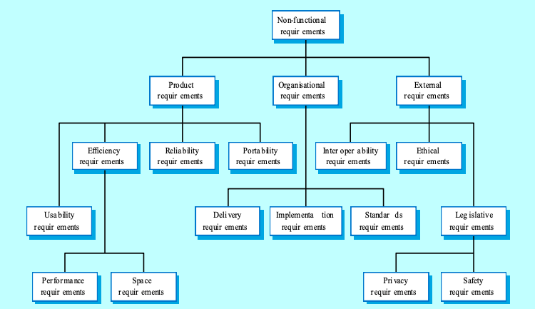
- Constraints on system services or functions, such as performance and reliability.
- Classifications:
- Product Requirements:
- Behavior and characteristics of the delivered product.
- eg: The user interface for LIBSYS shall be implemented as simple HTML without frames or Java applets.
- Organisational Requirements:
- Impact of organizational policies and standards.
- eg: The system development process and deliverable documents shall conform to the process and deliverables defined in XYZCo-SP-STAN-95.
- External Requirements:
- Requirements from external factors like legislation and interoperability.
- eg: The system shall not disclose any personal information about customers apart from their name and reference number to the operators of the system.
- Domain Requirements:
- Specific to the application domain and reflect domain characteristics. (healthcare, finance, etc)
- Examples: An inventory system requiring data integrity and reporting features.
- Requirements Engineering Processes
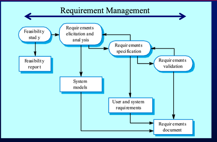
- Feasibility Studies:
- Determine if the proposed system is worthwhile.
- Assess organizational objectives, technology feasibility, and integration possibilities.
- questions to be asked
- What if the system wasn’t implemented?
- What are current process problems?
- How will the proposed system help?
- What will be the integration problems?
- Is new technology needed? What skills?
- What facilities must be supported by the proposed
system?
- Requirements Elicitation and Analysis:
- Elicitation: Gathering requirements through interviews, scenarios, and observation.
- Activities
- Requirements discovery
- The process of gathering information about the proposed and existing systems - sources of information include documentation, stakeholders and the specifications of similar systems (templates).
- Techniques
- Interview
- Closed interviews: pre-defined set of questions
- Open interview: no pre-defined questions
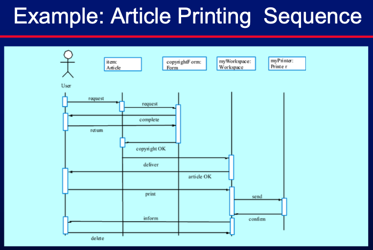
- Scenarios
- Real-life examples of how a system can be used
- Can be represented by
- Use case
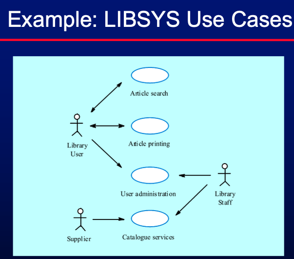
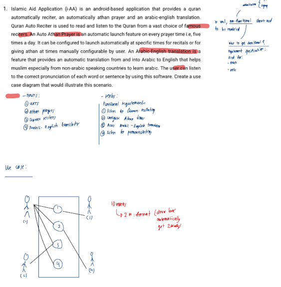
- Sequence diagram
- Observation
- Watching users interact with current systems to understand their needs and workflows.
- Ethnographic: Requirements derived from the way that people actually work rather than how the process definitions is
- Requirements classification and organisation
- Different perspectives from stakeholders such as interactors, indirect stakeholders, and domain experts. (viewpoints)
- Multi-perspective analysis helps in understanding and analyzing requirements comprehensively.
- Types of viewpoints
- Interactor viewpoints
- People or other systems that interact directly with the system. In an
ATM, the customers and the account database are interactor VPs.
- Indirect viewpoints
- Stakeholders who do not use the system themselves but who
influence the requirements. In an ATM, management and security
staff are indirect viewpoints.
- Domain viewpoints
- Domain characteristics and constraints that influence the
requirements. In an ATM, an example would be standards for inter-
bank communications.
- Prioritization and Negotiation
- Prioritizing requirements and resolving conflicts.
- Most important requirements are implemented first
- Requirements Documentation:
- Documenting requirements for input into the next round of the development cycle.
- Official statement detailing what is required from the system.
- Should define both user and system requirements without specifying design details.
- Follow standards like IEEE or DOD 2167.
- Requirements Validation:
- Ensures requirements are
- valid - Does the system provide the functions which best support the customer’s needs?
- consistent - Are there any requirements conflicts?
- complete - Are all functions required by the customer included?
- realistic - Can the requirements be implemented given available budget and technology
- verifiable - Can the requirements be checked? (is testing can be done?)
- Comprehensibility - Is the requirement properly understood
- Traceability - Is the origin of the requirement clearly stated
- Adaptability - Can the requirement be changed without a large impact on other requirements?
- Requirements Validation Technique
- Requirements reviews
- Systematic manual analysis of the requirements
- Both client and contractor staff should be involved in reviews
- Prototyping
- Using an executable model of the system to check requirements.
- Test-case generation.
- Developing tests for requirements to check testability.
- Hard to generate test translate to hard implementation.
- Requirements Specification:
- Gather, define, and validate software requirements.
- Format requirements for use by design, development, and testing teams.
- Generate refined business rules.
- Create refined workflow schemas.
- Develop detailed low-level requirements for guiding product development and delivery.
- Requirements Management:
- Planning
- Requirements identification
- How requirements are individually identified;
- A change management process
- The process followed when analysing a requirements
change;
- Traceability policies
- The amount of information about requirements relationships
that is maintained;
- CASE tool support
- The tool support required to help manage requirements
change;
- Traceability
- Concerned with the relationships between requirements, theirs sources, and the system design
- Types
- Source traceability • Links from requirements to stakeholders who proposed these requirements
- Requirements traceability • Links between dependent requirements;
- Design traceability • Links from the requirements to the design;
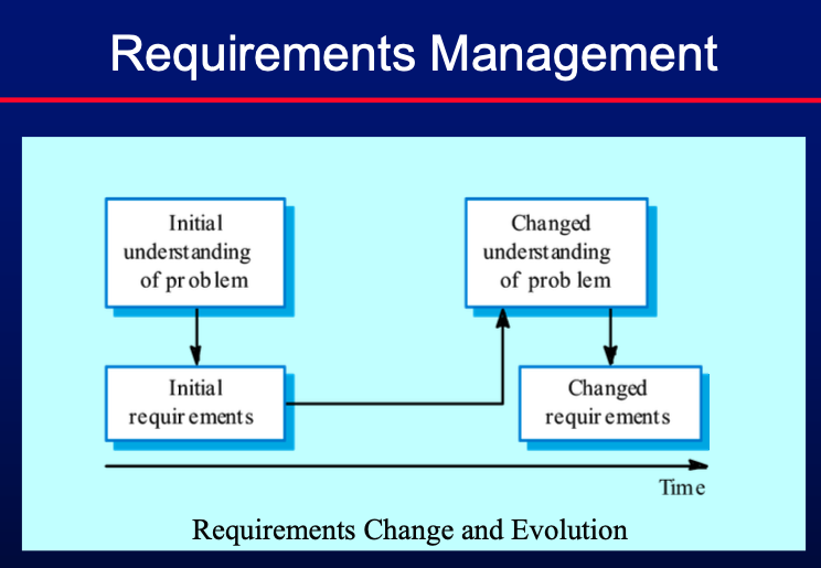
- Change and Evolution:
- Handling changes in requirements due to evolving business needs and technical constraints.
- Volatile requirements
- Stable requirements
- Derived from the core activity of the customer organisation
- May be derived from domain models
- E.g. a hospital will always have doctors, nurses, etc
- Unstable requirements
- Requirements which change during development or when the
system is in use.
- In a hospital, requirements derived from health-care policy
Chapter 7: System Models
-
Purpose: Helps analysts understand system functionality and communicate with customers.
-
System modelling present the system from different perspevtives:
- External: Shows system context/environment.
- Behavioral: Shows system behavior.
- Structural: Shows system/data architecture.
-
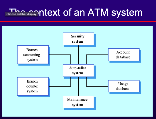
Context Models
- Definition: Illustrate the operational context of a system and what lies outside system boundaries.
- Influences: Social and organizational concerns can affect system boundary decisions.
- Architectural Models: Show the system’s relationship with other systems.
- Example:
-
Behavioral Models
- Describe overall system behavior.
- Types:
- Data Flow Diagram (DFD)
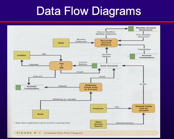
- Depict the flow of data through a system and the processing performed by the system.
- Central part of many analysis methods.
- Simple and intuitive for customers.
- Show end-to-end data processing.
- DFD Components:
- External Agents/Entities
- Outside person, organization, or system interacting with the system.
- Data Stores
- Inventory of data (e.g., files, databases).
- Processes
- Work performed by the system in response to data flows or conditions.
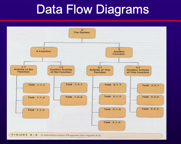
- Decomposition: Breaking a system into subcomponents and processes.
- Common DFD errors:
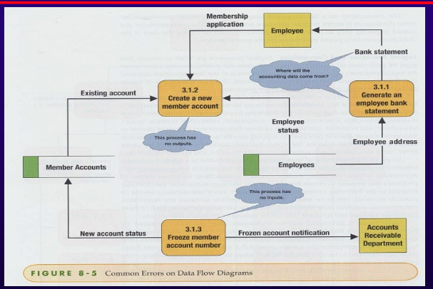
- Black Hole
- Process with inputs but no outputs.
- Named so because; enteres the process then diappears
- Has outputs but no inputs
- Gray Hole
- Process with insufficient inputs to produce outputs.
- Caused by:
- Misnamed process
- Misnamed inputs/outputs
- Incomplete facts
- Data Flow Conventions:
- Names: Unique, singular noun phrase for data flows; plural names for data stores.
- Legal Data Flow: All data must begin and/or end at a process.
- Data Structures: Arrangement of data attributes defining a single instance of a data flow.
- Divergent and Convergent Flows: Diverging or converging data flows.
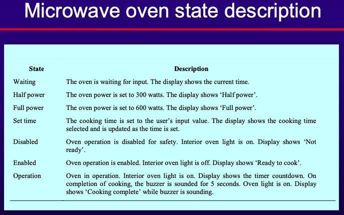
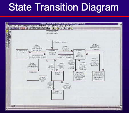
- State Machine Models
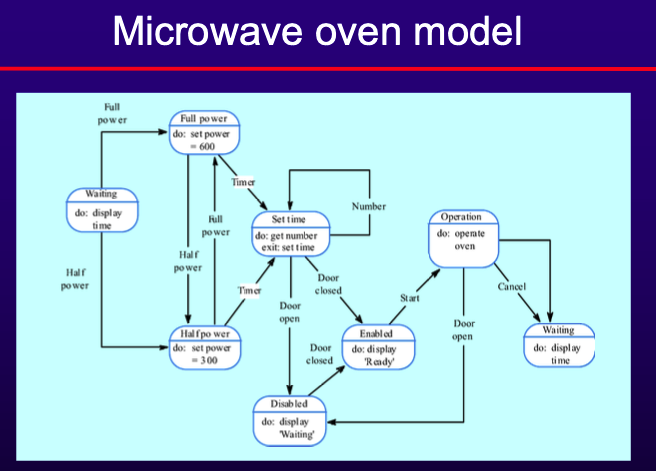
- Model system behavior in response to external and internal events.
- Often used for real-time systems.
- Components:
- States: System conditions.
- Events: Triggers for state transitions.
- Statecharts: Allow decomposition into sub-models with brief action descriptions.
-
Data Models
- Describe the logical structure of data processed by the system.
- First step in designing the database
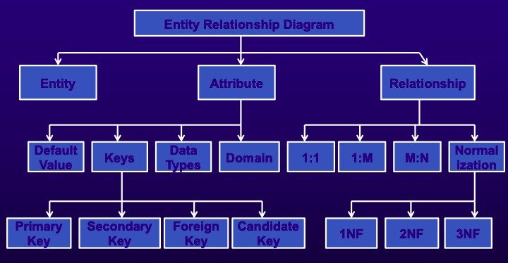
- Entity Relationship Diagrams (ERDs)
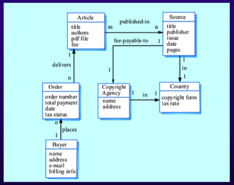
- Basic building blocks are entities, attributes, and relationships.
- Components:
- Entities: Objects about which data is collected (e.g., customers, products).
- Attributes: Characteristics of entities (e.g., customer name, address).
- Data Type: Type of data stored in the attribute.
- Domain: Legitimate values for the attribute.
- Default Value: Value recorded if not specified by the user.
- Key: Unique identifier for records.
- Candidate Key: Unique values, not repeated.
- Primary Key: Unique identifier for each row, used for record searching.
- Secondary Key: Not primary, used for narrowing search.
- Foreign Key: Primary key used in related tables.
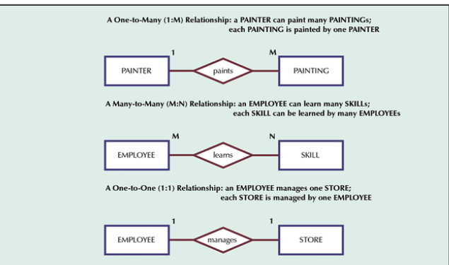
- Relationships: Associations among entities (e.g., 1:M, M:N, 1:1 relationships).
- Normalization:
- 1NF: No more than one value per attribute.
- 2NF: Non-primary-key attributes dependent only on primary key.
- 3NF: Non-primary-key attributes not dependent on other non-primary-key attributes.
-
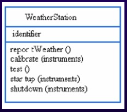
Object Models (UML)
Describe the system in terms of object classes and their associations.

- **UML Notations**:
    - **Use-Case Diagram**: Interaction between actors and software.
    - **Class Diagram**: Static relationships among classes.
    - **Sequence Diagram**: Object interactions as messages.
    - **State Diagram**: States and transitions due to events.
Chapter 8: Architectural Design
- What is Software Architecture?
- IEEE 1471-2000 Definition: The fundamental organization of a system, including its components, relationships, and principles governing its design and evolution.
- Perry and Wolf, 1992: A set of architectural elements with a particular form.
- Boehm et al., 1995: A collection of software and system components, connections, and constraints that satisfy stakeholders’ needs.
- Clements et al., 1997: The structure or structures of a system, comprising software components, their properties, and relationships.
- Software architecture is crucial due to various differences in projects, including:
- Scale
- Process
- Cost
- Schedule
- Skills and development teams
- Materials and technologies
- Stakeholders
- Risks
- Importance of Software Architecture
- Defines Major Components: Their relationships and interactions.
- Serves as a Blueprint: Guiding the system’s development.
- Addresses Quality Attributes: Ensuring the system meets desired quality attributes.
- Architectural Design Process: Identifying sub-systems and the framework for their control and communication.
- Output: A description of the software architecture.
- Architecture vs. Design
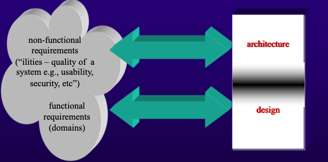
- Architecture: Focuses on non-functional requirements (e.g., usability, security).
- Design: Concentrates on functional requirements and their implementation.
- Architectural Design
- Early Stage in System Design: Links specification and design processes.
- Involves Major Components: Identifying and defining their communications.
- Advantages of Explicit Architecture
- Stakeholder Communication: Facilitates discussions among stakeholders.
- System Analysis: Allows analysis of non-functional requirements.
- Large-scale Reuse: Enables reuse across different systems. System Characteristics
- Designing a system architecture can be based on:
- Performance: Localize critical operations and minimize communications.
- Security: Use layered architecture with critical assets in inner layers.
- Safety: Localize safety-critical features in a few sub-systems.
- Availability: Include redundant components for fault tolerance.
- Maintainability: Use fine-grain, replaceable components.
- Architectural conflicts can happen if different goals is to be achieved
- Performance vs. Maintainability: Large components improve performance but reduce maintainability.
- Availability vs. Security: Redundant data improves availability but complicates security.
- Safety vs. Performance: Localizing safety features increases communication, degrading performance.
- Software architecture styles
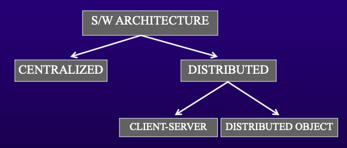
- Architectural styles define the overall structural organization of a software system. They are high-level strategies that dictate the relationship and interaction between different system components.
- Centralized systems
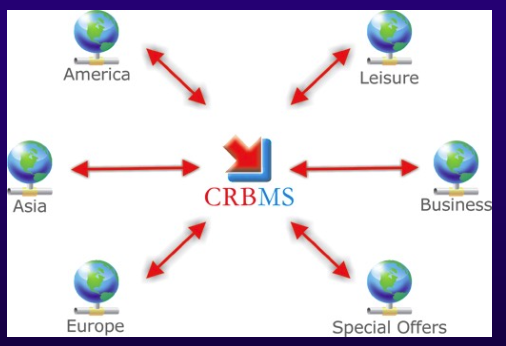
- Components are distributed across multiple locations and networks.
- Communication Hubs: Major communications are routed through central hubs.
- Synchronized Databases: Ensure data consistency across multiple sites.
- User Access: Multiple users can access data without interference.
- Distributed Systems Architecture
- 2 types
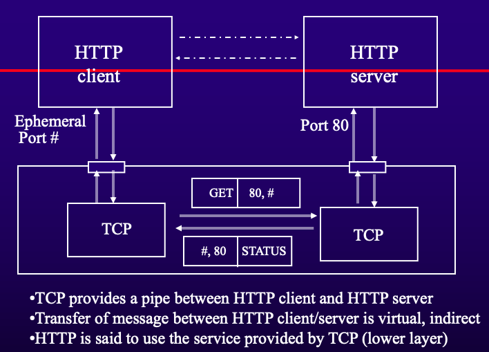
- Client-Server Architectures
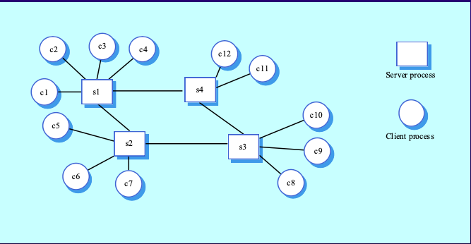
- Application Services: Provided by servers and used by clients.
- Terminology:
- Client: Makes requests.
- Server (Daemon): Receives and processes requests.
- Protocols: Rules governing interaction.
- Service: Provided by protocols.
- Layers’ Protocols: Each layer performs specific functions and builds on lower layers.
- Types of Servers
- Database Server: Hosts databases and executes data manipulation commands.
- Transaction Server: Ensures all database updates for a transaction succeed or fail as a whole.
- Application Server: Hosts application logic and services.
- Messaging or Groupware Server: Hosts e-mail, calendaring, and other workgroup functionalities.
- Web Server: Hosts websites.
- Different types of architecture of client-server
- Layered
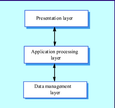
- Presentation Layer: User interface and interaction.
- Application Processing Layer: Application-specific functionality and business rules.
- Data Management Layer: Managing system databases.
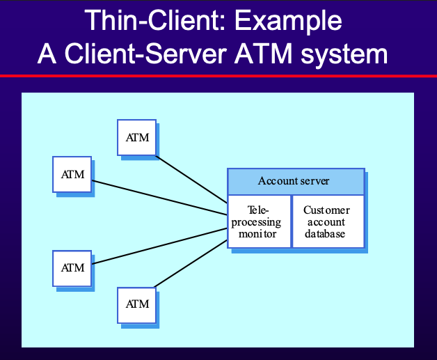
- Thin-client Model:
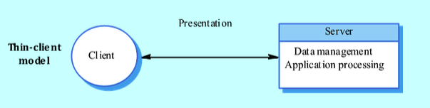
- Application processing and data management on the server; client handles presentation.
- Example
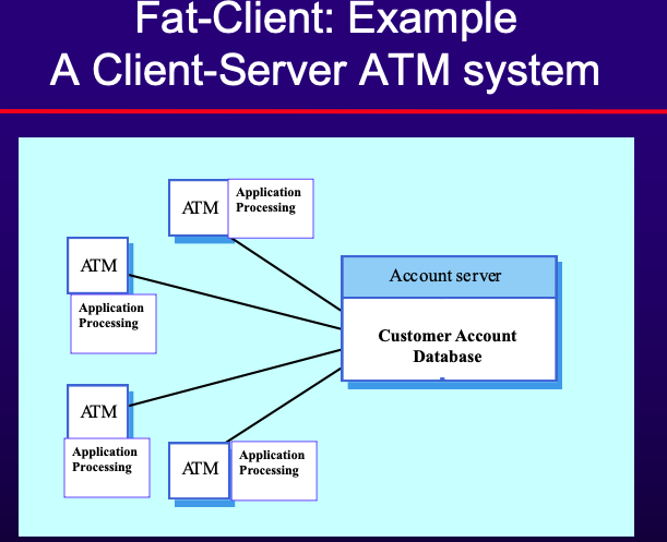
- Fat-client Model
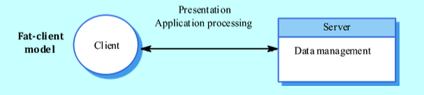
- Server handles data management; client handles application logic and user interaction.
- Example
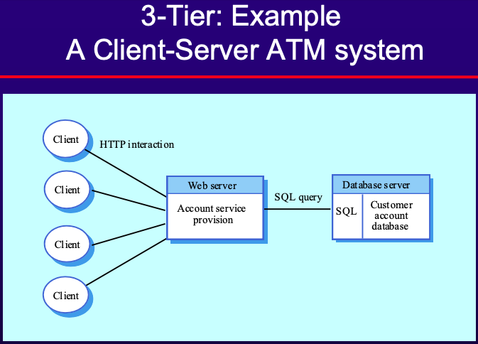
- 3-Tier Model:
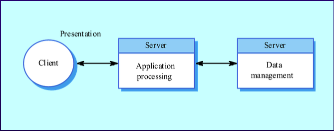
- Each application layer may execute on a separate processor, offering better performance and scalability.
- Example
- Distributed Object Architectures
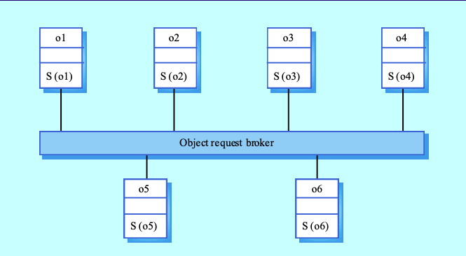
- No Client-Server Distinction: Objects provide and use services; objects provide and use services.
- Object Request Broker (ORB): Manages object communication.
- Every invoaction is passed to an ORB
- Responsible to
- Find the object implementation for the request.
- Prepare the object implementation to receive the
request.
- Communicate the data making up the request.
- Advantages:
- Allows teh ysstem designer to delays decisions on service provision
- Allows dynamic reconfigurationand
- Flexible and scalable.
- Characteristics
- Resource Sharing: Sharing hardware and software resources.
- Openness: Use of different vendors’ equipment and software.
- Concurrency: Enhancing performance through concurrent processing.
- Scalability: Adding new resources increases throughput.
- Fault Tolerance: Continuing operation after a fault occurs.
- Disadvantages
- Complexity: More complex than centralized systems.
- Security: More susceptible to external attacks.
- Manageability: Requires more effort for management.
- Unpredictability: Responses depend on system organization and network load.
- Software architecture pattern
- Architectural patterns provide solutions to common architectural problems. They offer templates for structuring components and their interactions but are more specific than styles.
- Three-tier architecture pattern
- The three-tier architecture pattern divides an application into three interconnected layers, each with distinct responsibilities
- Presentation Tier:
- Role: This layer handles the user interface and user interaction. It is responsible for presenting data to the user and interpreting user commands.
- Components: User interfaces such as web pages, mobile app interfaces, or desktop applications.
- Technologies: HTML, CSS, JavaScript, React, Angular, Vue.js, Swift, Kotlin, etc.
- Application Logic Tier (Business Logic Tier):
- Role: This layer contains the core functionality and business logic of the application. It processes user inputs from the presentation layer, applies business rules, and determines the appropriate data to retrieve or update in the data layer.
- Components: Application services, business rules, workflows.
- Technologies: Java, C#, Python, Node.js, .NET, Spring Boot, Express.js, etc.
- Data Tier:
- Role: This layer manages data storage and retrieval. It interacts with databases or other data sources to store and fetch data as needed by the application logic layer.
- Components: Databases, data access objects (DAOs), repositories.
- Technologies: SQL databases (MySQL, PostgreSQL), NoSQL databases (MongoDB, Cassandra), ORM tools (Hibernate, Entity Framework), etc.
- Networks
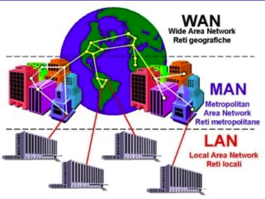
- Communication Links: Devices exchange data along connections.
- Types of Networks
- LAN (Local Area Network): A network connecting devices within a small geographic area, like an office or home. For example inter-office file sharing network
- MAN (Metropolitan Area Network): A network covering a city or large campus, larger than a LAN but smaller than a WAN. For example a network infrastructure connecting various institutions..
- WAN (Wide Area Network): A network that spans a large geographic area, connecting multiple LANs. For example a corporate network connecting different offices in different cities.
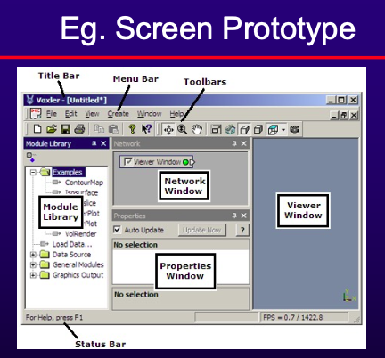
Chapter 9: UI Design
- UI should match the skills, experience, and expectations of its anticipated users.
- Users often judge a system by its interface rather than its functionality.
- Poorly designed interfaces can cause catastrophic errors and lead to software being unused.
- UI Problems (According to Galitz)
- Excessive use of computer jargon and acronyms.
- Non-obvious or less-than-intuitive design.
- Inability to distinguish between alternative actions (“what do I do next?”).
- Inconsistent problem-solving approaches.
- Design inconsistency leading to confusion, panic, frustration, boredom, misuse, and abandonment.
- UI Design Issues
- Address two primary problems in interactive systems design:
- How should information from the user be provided to the computer system?
- How should information from the computer system be presented to the user?
- Solutions:
- Understand users and their tasks.
- Involve the user in interface design.
- Test the system on actual users.
- Practice iterative design.
- Human Factors to consider in Interface Design
- Limited short-term memory: People can remember about 7 items instantaneously; presenting more can lead to mistakes.
- People make mistakes: Inappropriate alarms and messages can increase stress and cause more errors.
- People are different: Design should consider a wide range of physical capabilities.
- Interaction preferences vary: Some users prefer pictures, others prefer text.
- UI Design Principles
- User Familiarity: Use user-oriented terms and concepts rather than computer jargon.
- Consistency: Ensure commands, menus, and formats are consistent.
- Minimal Surprise: Commands should operate in predictable ways.
- Recoverability: Provide resilience to user errors with features like undo, confirmation for destructive actions, and ‘soft’ deletes.
- User Guidance: Include help systems and on-line manuals.
- User Diversity: Support different interaction facilities for diverse users, such as larger text for users with seeing difficulties.
- UI Design Guidelines
- Ensure users know what to do next.
- Provide clear feedback on data entry and task completion.
- Use consistent screen layouts for instructions and messages.
- Anticipate user errors and provide efficient error messages.
- Prevent users from proceeding without correcting errors.
- Use consistent terminology and navigation control schemes.
- Clearly distinguish between options like “NO” and “CANCEL”.
- Information Presentation
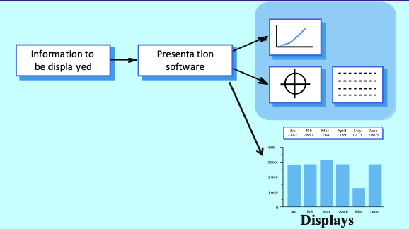
- Concerned with presenting system information to users.
- Information can be static (unchanged during a session) or dynamic (changes during a session).
- Static Information: Initialized at the beginning of a session, may be numeric or textual.
- Dynamic Information: Changes during a session and must be communicated to the user, may also be numeric or textual.
- Analogue vs. Digital Presentation
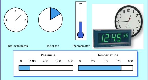
- Digital Presentation: Compact, communicates precise values.
- Analogue Presentation: Provides an at-a-glance impression, shows relative values, and highlights exceptional data.
- Colour Displays
- Colour adds an extra dimension and helps understand complex information structures.
- Use colour to highlight exceptional events but avoid overuse and dependence on colour alone (as 10% of people are colour blind).
- Error Messages
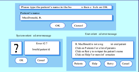
- Critical for user acceptance. Should be polite, concise, consistent, and constructive.
- Design messages based on the user’s background and experience.
- Dialogue Tone and Terminology
- Use simple, grammatically correct sentences.
- Avoid being funny, cute, or condescending.
- Avoid computer jargon and most abbreviations.
- Be consistent with terminology and phrase instructions carefully using appropriate action verbs.
- GUI: Styles & Considerations
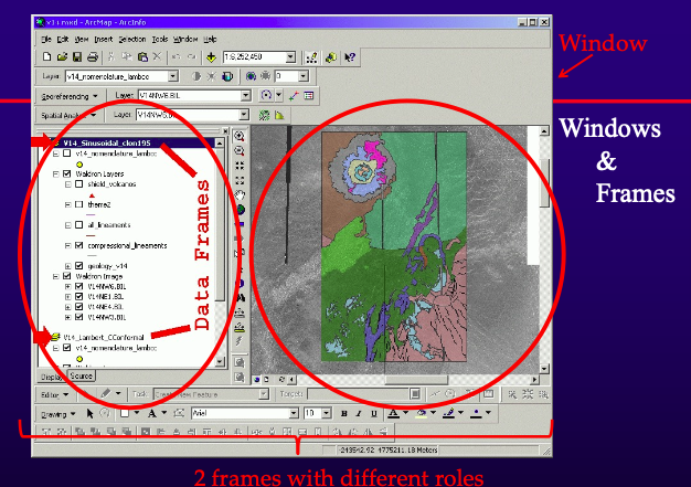
- Various styles include windows and frames, menu-driven interfaces, toolbars, and iconic menus, hypertext and hyperlink menus, instruction-driven interfaces, and question-answer dialogues.
- UI Design Process
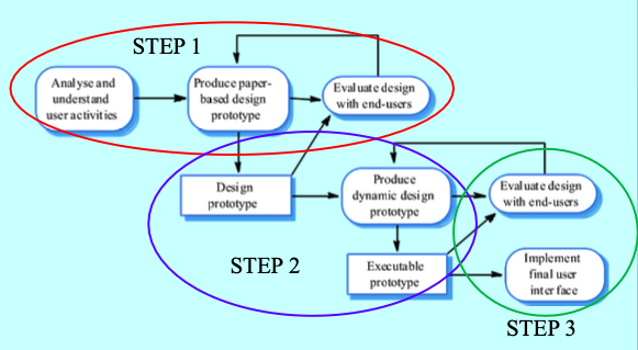
- An iterative process involving close liaison between users and designers.
- Core activities:
- User Analysis: Understand user tasks..
- Describe user analyses in terms users and designers can understand, using scenarios.
- Analysis Techniques:
- Task analysis (models steps in completing a task).
- Interviewing and questionnaires.
- Ethnography (observing and questioning users at work).
- UI Prototyping: Develop prototypes for user experimentation.
- Allow users to gain direct experience with the interface.
- Use paper prototypes early in the process, followed by more sophisticated automated prototypes.
- UI Evaluation: Experiment with prototypes and obtain user feedback.
- Assess the suitability of the user interface design.
- Obtain user feedback through questionnaires, video recordings, code instrumentation, and online feedback mechanisms.
Chapter 10: Systems Construction, Implementation, and Testing
-
Systems construction, implementation, and testing are crucial phases in the software development lifecycle. These phases ensure that the system is built correctly, integrates well with existing components, and meets the requirements and expectations of users.
-
Systems Construction
- System construction involves the development, integration, and testing of system components. It is triggered by the approval of physical design specifications.
- Major Aspects:
- Programming: Writing code to develop system functionalities.
- Testing: Ensuring the system works as expected.
- Integration: Combining various software components into a cohesive system.
- Construction Phase
- Types of Software:
- New Software: Developed from scratch.
- Updated/Enhanced Software: Modifications to existing software.
- Buy/Lease Software: Acquiring third-party software.
- Tasks:
- Programming, Build and Test Networks:
- Existing Network: Use existing infrastructure, skipping this task.
- Modified/New Network: Implement and test new or modified network architecture based on technical design specifications.
- Build and Test Databases:
- Existing Database: Verify and test the current database.
- New or Modified Databases: Develop and test new or modified databases.
- Install and Test New Software Packages:
- New/Purchased/Leased Software: Check compatibility with networks and databases.
- Updated/Enhanced Software: Test new functionalities and features.
- Write and Test New Programs:
- Develop and refine prototype programs through comprehensive testing.
-
Systems Implementation
- System implementation is the installation and delivery of the entire system into production, ensuring a smooth transition to operational status.
- Implementation Phases**:**
- Conduct System Test:
- Perform a final system test covering all aspects of the system and its environment.
- Communicate testing issues to team members.
- Prepare Conversion Plan:
- Develop a plan to transition the new system into operation.
- The plan includes database installation, end-user training, and system acceptance tests (verification, validation, audit).
- Install Databases:
- Populate new system databases with existing data.
- Train System Users:
- Provide training and user manuals for the new system.
- Convert to New System:
- Gather feedback from system owners/users to benchmark the new system.
- Installation Strategies:
- Abrupt Cut-Over Conversion: Immediate switch from the old to the new system - high risk.
- Parallel Conversion: Both old and new systems run simultaneously until the new system is verified.
- Location Conversion: System is implemented at one location first, then expanded.
- Staged Conversion: The system is introduced in phases using various strategies (abrupt, parallel, location).
-
Software Testing
- Software testing is the process of validating and verifying the quality of the software to find bugs and ensure the software works as intended.
- Activities
- Execute Software with Inputs: Use inputs that simulate actual operational conditions.
- Compare Outputs: Verify produced outputs against expected outputs.
- Compare States: Check resulting states against expected states.
- Measure Execution Characteristics: Evaluate aspects like memory usage and execution time.
- Testing results
- Pass: Actual results match expected results.
- No Pass: Actual results differ from expected results.
- Testing Scope
- Testing in the small
- Exercising the smallest executable units of the system
- Unit Testing:
- Testing individual components in isolation to find faults and ensure correct functionality.
- Usually performed by programmers
- Objectives:
- Finding faults
- Assure correct functional behaviour of units
- Object Class Testing
- Ensures complete test coverage of a class by testing operations, attributes, and states.
- Testing the build
- Finding problems in the interaction between components
- Integration Testing:
- Testing combined units to detect interface errors and ensure functionality.
- Performed by programmers or testing gorup
- Objectives
- Detect interface errors
- Assure the functionality of the combined units and third-party components
(e.g.,COTS, other systems)
- Interface Testing
- Detects faults due to interface errors, particularly in object-oriented development.
- Examples
- Interface misuse. A calling component calls another component and makes an error in its use of its interface e.g. parameters in the wrong order.
- Interface misunderstanding. A calling component embeds assumptions about the behaviour of the called component which are incorrect.
- Timing errors. The called and the calling component operate at different speeds and out-of-date information is accessed.
- Testing in the large
- Putting the entire system to test
- System Testing
- Testing the entire system’s functionality, performance, reliability, and security.
- Performed by a separate testing group
- Objectives
- Find errors in the overall system behaviour
- Establish confidence in system functionality
- Validate non-functional system requirements
- Acceptance Testing
- Operating the system in the user environment to evaluate if it meets customer criteria.
- Performed by end-user
- Objectives
- Evaluate whether the system meets the customer criteria
- Determine whether the customer will accept the system
- Regression Testing
- Testing modified versions of the system to ensure changes haven’t introduced new errors.
- Performed by the system itsefl or a regression test group
- Objective
- Ensure changes haven’t introduced new errors.
- Structural Testing
- Types
- Statement Testing: Ensure every statement in the program is executed.
- Branch Testing: Ensure every branch is executed.
- Expression Testing: Ensure every expression is tested with a variety of values.
- Path Testing: Ensure all paths of the program are executed.
- Testing Methods
| Feature |
Black Box Testing |
White Box Testing |
| Knowledge Requirement |
Internal workings of the application are not required to be known. |
Tester has full knowledge of the internal workings of the application. |
| Alternate Names |
Closed box testing, data-driven testing, functional testing. |
Clear box testing, structural testing, code-based testing. |
| Performed By |
End users, testers, and developers. |
Normally done by testers and developers. |
| Approach |
Based on external expectations; internal behavior of the application is unknown. |
Based on knowledge of internal logic and code structure. |
| Time Consumption |
Generally less time-consuming. |
Generally more time-consuming and exhaustive. |
| Suitability |
Not suited for algorithm testing. |
Suited for algorithm testing and detailed code examination. |
| Coverage |
Trial and error method |
Structural coverage including statement, branch, path, and data-flow testing. |
- Test Case Template:
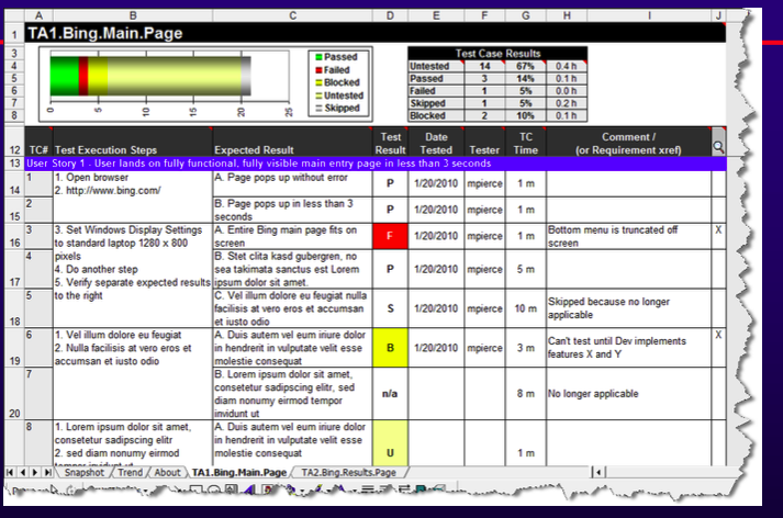
- Set of inputs, execution conditions, and expected results for a particular testing objective.
- Terminologies:
- Fault/Bug: An imperfection in the code leading to failure.
- Error: Incorrect system state not yet observed.
- Failure: Observable failure to deliver expected service.
- Test Case: Set of inputs and conditions to achieve a testing objective.
- Test Suite: Collection of related test cases.
- Test Driver/Stub: Simulates the activity of missing components for integration testing.
- Test Strategy: Algorithm to create test cases from representations or implementations.
-
Analysis model
-
Use case
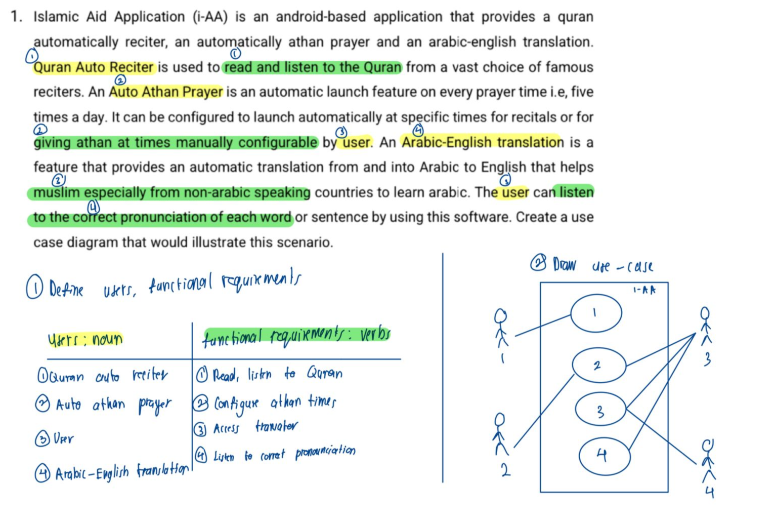
- Define users and functional requirements
- Users: nouns
- Functional requirements: verbs
- Draw use case
-
ERD
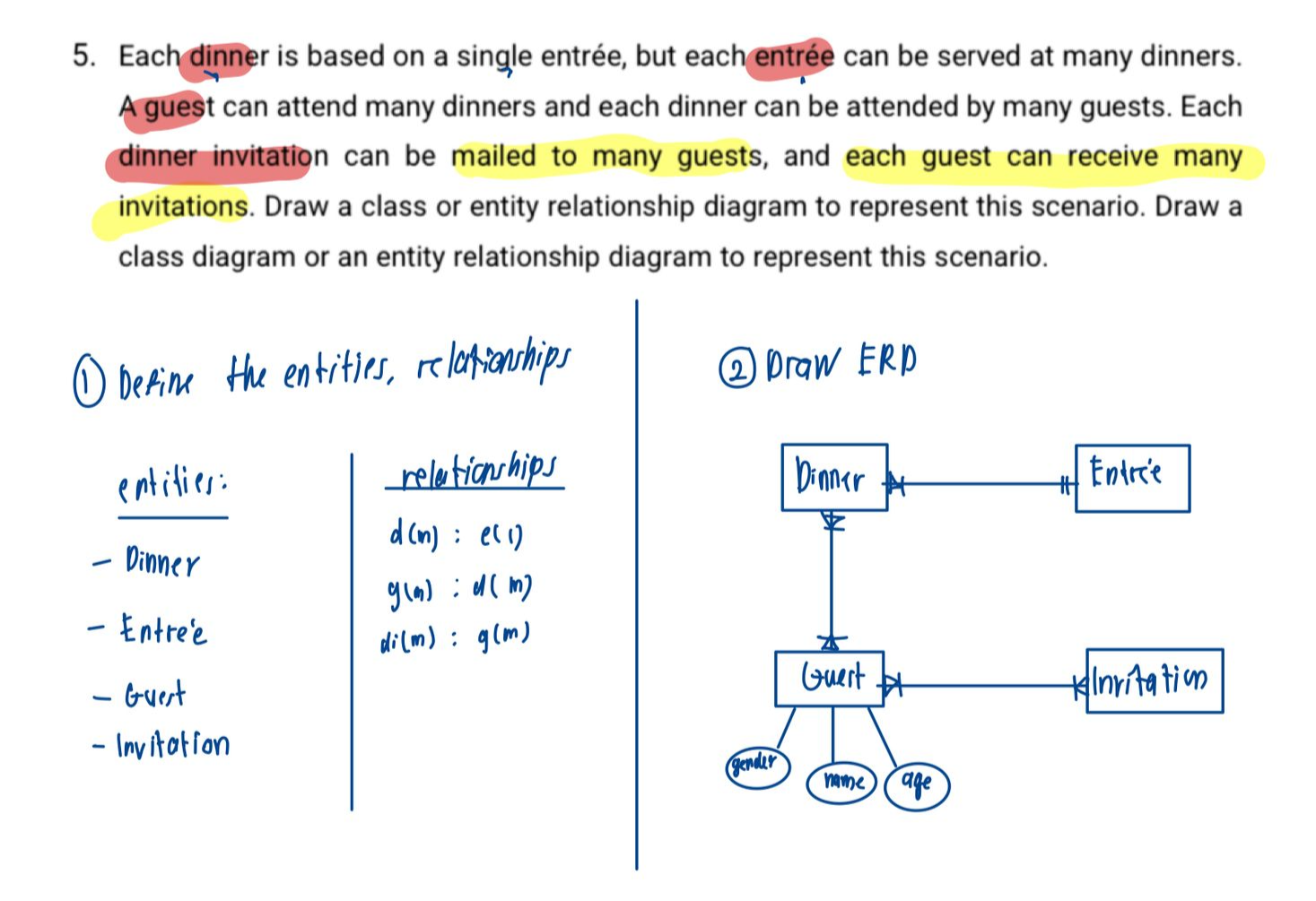
- Define entities, relationships
- Draw ERD
-
Excercises
-
GOALS
-
Analysis model
- Use case
- Define users and functional requirements
- Users: nouns
- Functional requirements: verbs
- Draw use case
- ERD
- Define entities, relationships
- Draw ERD
-
Test cases
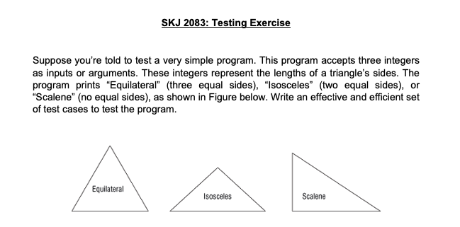
| Test Case |
Step No |
Step Description |
Expected Results |
| Equilateral |
1 |
Input: (3, 3, 3) |
Output: “Equilateral” |
| Equilateral |
2 |
Input: (10, 10, 10) |
Output: “Equilateral” |
| Isosceles |
3 |
Input: (3, 3, 2) |
Output: “Isosceles” |
| Isosceles |
4 |
Input: (5, 5, 3) |
Output: “Isosceles” |
| Isosceles |
5 |
Input: (4, 4, 2) |
Output: “Isosceles” |
| Isosceles |
6 |
Input: (6, 6, 4) |
Output: “Isosceles” |
| Isosceles |
7 |
Input: (10, 10, 5) |
Output: “Isosceles” |
| Scalene |
8 |
Input: (3, 4, 5) |
Output: “Scalene” |
| Scalene |
9 |
Input: (5, 7, 10) |
Output: “Scalene” |
| Scalene |
10 |
Input: (6, 8, 10) |
Output: “Scalene” |
| Scalene |
11 |
Input: (7, 10, 5) |
Output: “Scalene” |
| Scalene |
12 |
Input: (9, 12, 15) |
Output: “Scalene” |
| Invalid |
13 |
Input: (1, 2, 3) |
Output: “Invalid” |
| Invalid |
14 |
Input: (1, 1, 2) |
Output: “Invalid” |
| Invalid |
15 |
Input: (5, 1, 1) |
Output: “Invalid” |
| Invalid |
16 |
Input: (0, 0, 0) |
Output: “Invalid” |
| Invalid |
17 |
Input: (-1, -1, -1) |
Output: “Invalid” |
| Invalid |
18 |
Input: (2, 2, 5) |
Output: “Invalid” |
| Invalid |
19 |
Input: (0, 5, 5) |
Output: “Invalid” |
| Edge Case |
20 |
Input: (1, 1, 1) |
Output: “Equilateral” |
| Edge Case |
21 |
Input: (1000000, 1000000, 1000000) |
Output: “Equilateral” |
| Edge Case |
22 |
Input: (1000000, 1000000, 1) |
Output: “Isosceles” |
| Edge Case |
23 |
Input: (1000000, 999999, 2) |
Output: “Scalene” |
-
Architectural
-
- Describe the difference between architecture and design. (5 Marks)
- Architecture is the high-level structure of a software system, focusing on how components interact and fit together. It primarily addresses the non-functional requirements, such as scalability, performance, security and maintainability. It defines the overall framework within which the software operates, determining how the system’s component will interact and communicate
- Design focus on functional requirements. It invovles the detailed planning and specification of individual components and their interactions within the architectural framework. It deals with the implementation details, such as algorithms, data structures and user interface, ensuring each components performs its intended fucntion correctly
-
- Describe the difference between three types of network. (6 Marks)
- LAN (Local Area Network): A network connecting devices within a small geographic area, like an office or home. For example inter-office file sharing network
- MAN (Metropolitan Area Network): A network covering a city or large campus, larger than a LAN but smaller than a WAN. For example a network infrastructure connecting various institutions..
- WAN (Wide Area Network): A network that spans a large geographic area, connecting multiple LANs. For example a corporate network connecting different offices in different cities.
-
-
In a three-tier architecture, each of the application needs to be executed on a separate architecture layers. Explain each tier. (9 Marks)
-
Presentation layer
This layer handles what is shown to the user, i.e; the user interface. It is responsible for presenting data to the user and interpreting user commands. Technologies commonly used for web applications are HTML, CSS, and JavaScript
-
Application logic layer
This layer handle the application logic from or to the user. It is responsible for processing user input, perform any data manipulation, data storing or data retrieval. Technologies commonly used for web applications are JavaScript, Node.js, Express.js
-
Data layer
This layer handle the data storing fucntionality. It is responsible to store any data from the user and from the application itself. It will proivide the data needed upon retireivel, storing new data, or update data from the application layer. Technologies commonly used are MySQL, MongoDB,
-
- Design a standard/basic web application architecture. (10 Marks)
- Presentation layer
- Technologies: React
- Responsibilities: User interface, user experience, handling user interactions.
- Application logic
- Web server
- Technologies: Nginx
- Responsibilities: Serving static content, reverse proxy, load balancing.
- Server side component (backend)
- Node.js
- Responsibilities: Processing requests, executing business logic, interacting with the database.
- APIs:
- Technologies: RESTful APIs
- Responsibilities: Facilitates communication between the client and server, integrates with third-party services.
- Data:
- Technologies: MongoDB
- Responsibilities: Data storage, retrieval, and management.